Ekahau Site Survey (ESS) is arguably one of the leading Wi-Fi site survey packages on the market. It provides many features to assist the WLAN designer/surveyor to ensure that their WLAN is operating effectively. One of these features is the ability to predict interference caused as network load increases.
I’ve been using this feature for a good long time but now I question it’s effectiveness and the usefulness of it’s output. I’m not convinced it’ algorithms lead to accurate estimations – possibly invalidating some of the work I have used it for in the past. This article will examine the feature and look at the potential issues and I invite comment on whether you think likewise – or have I got it wrong somewhere?
The Feature – Simulated Interference
The feature in question is ESS’s tool which predict drops in Signal to Noise Ratio (SNR) as a network gets busier, based upon the locations, channels and power levels of APs. This predictive tool appears in a number of visualisations and in theory, allows one to adjust the simulated load on the network from zero to 100%. The visualisations show the decreasing network performance as the load increases, allowing you to evaluate the effectiveness of your designs or compare different designs with respect to interference
Why is this important
The reason this tool is important is because we expect some drop off of SNR on a large, busy and (or) high density networks. The mechanisms for this are out of the scope of this post, but in short, transmissions from distant devices on the same channel will cause interference, either as noise (and a drop in SNR) or channel contention.
Therefore, when designing a WLAN and specifying that it must meet say, SNR 25 across the site, it is useful to be able to test it under simulated loaded conditions – a feature which Ekahau handily happens to have.
However, I believe that Ekahau’s implementation of this is deeply flawed.
There are two main issues with the tool. Firstly, I have no idea how ESS quantifies network load. Secondly, I believe the implementation of SNR modelling is way off. I will discuss these two points now in more detail.
1:- How are we measuring load
Since I have used the tool I have been advised that a network load of 30% is very high. And, based upon this, have always been advised to use 20% to validate my designs.) I have always wondered what this really means, and so I have asked Ekahua. The response I received back was effectively “it’s proprietary, so we can’t really tell you, but consider 30% as high…and 50% as insanely high – like you’d get in a stadium environment”
What can this possibly mean? I think my WLAN is reaching capacity if the “duty cycle” is reaching 80% or so – nearly maxed out. (Note – I’m not making reference to actual throughput or goodput on the network here, just pain old amount-of-airtime-used-up!) So, even if we assume we’re talking about “duty cycle” or saying “30% of available airtime is used”, I want my WLAN to perform well with as close to 100% load as possible; offering optimum network capacity. I’m therefore not interested to see if it works with 30% of something – I need to know the impact on SNR when things are really busy – as this is when the WLAN is most likely to fail.
So, it’s a bit like an engineer building a railway and telling the customer:-
“it’s designed to be safe at Slow speeds and Fast speeds but not Very Fast speeds, but I can’t quantify those measures for you”.
2:- SNR Modelling
The second issue is with the actual modelling of the effect of adding more AP’s to the network SNR.
Let us look at a really simple example to illustrate the problem.
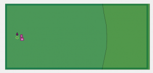
Single AP on channel
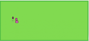
Here we have a very simple ESS simulation of a generic dual band 802.11n AP. It’s installed on it’s own in a 25m long room. This visualsiation is showing the SNR according to Ekahau’s default scale – the dark green meaning 50+ SNR. We’re looking at 2.4GHz only, with a network load simulated at 20% No surprises so far; SNR looks really good.
So, let’s add another AP on the same channel.
.
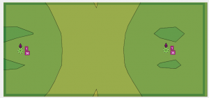
Two APs on channel
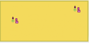
You can see here that we’ve added another AP onto the same channel and the SNR has dropped off. It is now sitting at between 30 and 35 dB across most of the site and is weaker in the middle where the signals from the two APs will be closest in strength.
At first glance this does look quite sensible as APs (and clients!) on the same channel will interfere with one another.
But…
What mechanism is causing the signal strength to drop off by 15-20dB? (Or more! – note that our original scale was set to max out at SNR 50+).
When a signal from AP 1 is heard at AP 2, two things can happen. Either it will be de-modulated as 802.11 traffic and AP 2 will defer transmitting until AP 1 has finished, or, if the received signal from AP 1 is too weak then AP 2 will not be able to interpret it; and it will just add to the background noise level.
In this example, wherever you’re positioned in our simulated room, whether an AP or client device – you’d hear AP 1 loud and clear. Even if AP 1 was sending out data to another client at a high data rate which you could not understand (i.e. demodulate as 802.11 traffic successfully), the packet headers would still be understood as packet headers are sent at the lowest ‘basic rate’ which the network supports. Having decoded these headers you’d be be deferring your transmissions and would not be affected by increased noise.
So, arguably, the SNR in this example should not drop at all. If all the clients can hear one-another there will be simply lots of contention for the channel? (There are no distant APs, no weak signals to increase the background noise level.)
Increase the load!
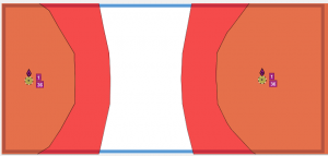
To make matters worse, look what happens when I pump up the simulated load to 100%
The same simulation with the same two APs but now the network load is set to 100%. The SNR has dropped off to almost nothing. Why is this? Assuming that the devices are obeying the 802.11 CSMA/CA rules and waiting for one another to transmit, this massive drop-off of SNR would not happen. It might represent a situation where you had a hidden node transmitting constantly – in which case, let’s call it the “hidden node impact” visualisation, however, the slider representing % transmission time would still not be useful as we still have two distinct scenarios – we’d either have awful SNR when the hidden node transmitted at the same time – or not; a binary split.
(Actually, i’m liking the idea of a hidden node placement simulator…)
Deploy more APs!
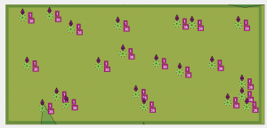
OK, so another thing I which interested to find out is was what happens if I deploy more APs? Resetting the network load to 20%, I now place down another 20 or so APs on the same channel into the ESS simulation. And this is what happens:-
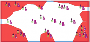
As I added these in I could see that the SNR visualisation was slowly homing in on some SNR level around 30, as shown by the image on the left. When increasing the load upwards again using the slider bar, the SNR dropped off more quickly – reaching the stage where it was almost zero at around 75% load.
Simulated SNR in summary
So, I guess I don’t really know how to interpret these results. It looks like ESS is reducing the SNR by a percentage of the strongest competing signal that is received at any one place – so by say 20% of -50dBm if we’ve set load to 20%.
What I do know is – I don’t really want to use the simulated load metric in my designs in it’s current state. I’d be really interested to hear other views and opinions – am I reading the tool right?
Also, the Interference Visualisation…
Let’s just take a quick look at the other visualisation Ekahau provides which uses simulated noise – ESS’s “Interference / Noise” visualisation. This should be a really useful tool as we site survey on quiet networks and so our reports will tend to show clearer RF environments than we might expect in reality. It would be really great to be able to predict the noise level as the network got busier.
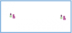
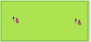
These two pictures show the “interference” with no load, and a little load. With zero load on the network there is no interference – shown by a blank visualisation (on the left). With a little load (a few percentage points) we can see the visualisation turn green (right). ESS scales this by default to -100dBm (good) as green to -40dBm to deep red (bad). With little load, the interference is showing green at about -95dBm.
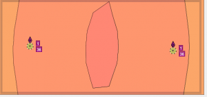
Now let’s pull that slider all the way to 100% to make Ekahau simulate 100% network load.
ESS shows this as bad bad bad – an interference of up to -40dBm.
What does this really mean?
But again, what does this really mean? It looks like ESS is once again doing simple math(s) on the numbers. Given little load then it’s assuming the “interference” is about -95dBm; ie, optimum background noise level. Then as we increase load it’s simple increasing the noise level by a percentage of the signal strength of the competing AP. Which isn’t how it works at all! Again, this might show us how badly an area might be affected by the presence of a hidden node or if one AP decided simply to transmit over the top of another, but it massively mis-represents how this stuff actually works and only helps to add strength to general mis-understanding around 802.11 “interference”.
What would we expect to happen
I might have this wrong, but I would expect that the maximum SNR drop due to Co-Channel Interference to be about 10dB, given that:-
– Background noise is about -95 to -100dBm
– Receive Sensitivity is probably about -90dBm for a 1mpbs transmission
– If a signal comes in at -91dBm, it’s noise – reducing our SNR by 9dB
– If a signal comes in at -90dBm or above, it’s Wi-Fi, so we demodulate it and set our NAV timer to defer transmissions; it’s not “interfering noise”
(A bit simplified – but should illustrate my point!)
Whilst we can argue about the exact numbers or quibble about different client devices, receive sensitivities, basic rates and the like, I believe the general principle holds – the SNR loss due to interference from distant clients on the same channel will be limited.
What I really need…
Despite all this, I still believe that ESS is probably the best site survey tool on the market. It has a good set of set of features; it’s generally well written and rarely crashes. (There is little worse than losing an hours’ worth of live survey data!)
And it does have one other great new feature that really does help to show the effects of “interference”, or rather “Co-Channel-Co-Operation”. That feature is the new “Channel Overlap” view.
Ekahau’s Channel Overlap view
Let’s look at our simple simulation with the new Channel Overlap view.
This view allows you to set the definition of “overlap” with respect to the received signal strength at which we say the channels overlap, in dBm. (As well as some other features I’ve not looked into). I tend to go for -80dBm as my definition. (I’d be interested to hear thoughts on other numbers to plug in!). Given this, this is what it looks like with one and two of our generic APs in the simulation, both on channel 1.
I think Ekahau have this spot on. Given a single AP – everything is green. Add just one more, and it turns nicely yellow – flagging “whooo, hold on, possible performance issue here!”.
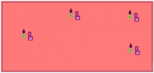
Add in two more, for a total of 4 and it goes all red -the defualt scale for 4+ APs on channel, as below.
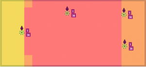
And if we change our definition of “overlapping” to be -50dBm (just to illustrate), we get something like the below.
The red area is now the area where all four APs are visible with a signal strength of -50dBm.
What’s great also is if I mouse over any point I get a list of the BSSID’s visible at this point.
Why do I want this
It is my opinion that many networks are over-provisioned; extra AP plugged in to add capacity. This view clearly shows up these situations, highlighting where APs and clients are simply going to queue up for access to the air to talk.
So what does this all mean then
I think the main conclusion is that in order to allow for SNR degradation on a busy WLAN I need to simply design in a higher SNR threshold and not try to simulate any. Instead of SNR 20 as acceptable, I might want to look at SNR 25 to 30. (Again I’d be interested in ideas as to exactly what to plug in here).
It would be nice if Ekahau could sort two things; first and foremost, update the SNR view with a more sensible depiction of SNR drop off – maybe by adding into the model a variable for “lowest basic rate”, or something to account for “Successful demodulation threshold”.
It would also be interesting to develop the Signal Overlap view to show effective capacity; modelling things like beaconing overheads, probing, etc to allow the designer to see how efficient their design would be.


It seems that their proprietary method is redefining SNR, or at least it is trying to add several “intangibles” into the mix.
Two questions I have are 1) Does changing the Basic rate(s) in the simulation affect the SNR score? 2) Are reflections, based upon room geometry or materials, considered (or obviously considered)in the calculations?
If the answer is no for either question I think their simulation is just trying to be useful in most circumstances, based upon their own experience – which might be hard to express in writing.
As far as aiming for 100% utilization I would say that a maximum of 80% would be a more realistic threshold, as has been seen with other technologies limited in resources. e.g. fragmented disks
Thanks for your feedback Howard. The answers to your questions are:-
1) Nope, you can’t model the basic rates in ESS. They would definitely a useful thing to add to the model.
2) All this sort of thing is hidden within ESS, but presumably must be modelled with some kind of algorithm to give ESS any chance of being at all accurate.
I agree re: 80% Utilisation; realistically you’ll never get near 100%; 100% just makes a clearer illustration of the point.
Hi Jon,
I develop the ESS network modeling features. I am aware that interference visualizations do not fully cover the behavior of the WLAN channel. To be honest, the interference calculations have been as-is for years, and could be better implemented to meet the today’s needs. We are planning to improve them in future releases.
It is fair to say that network load is not the same thing as WLAN airtime. The problem is how to control the amount of traffic in the network using a single control? It is not possible to say that the airtime of each access point (AP) is for example 50%. The medium access control prevents that when the APs are on interfering channels. We have some ideas how this could be presented to the user but we also would like to hear your views as a ESS user.
Just to throw some implementation options out there: One such option would be the user setting the numbers and types of devices in the network (like in Capacity Requirements), we could use the airtime calculations (which we already do) and calculate interference based on that information. However, for some users this would require too much input. An alternative to that would be a simple slider, like one we have today, but with different, more real-world-representing calculations.
If you would like to give input on how the improved ESS interference estimation should be controlled by the user you could send me a private email. Thanks for your feedback.
Timo Vanhatupa, Dr. Tech.
Senior Research Scientist
Ekahau Wi-Fi Tools
Hi, Timo.
This topic has re-surfaced with Jon & I discussing some other matters.
Can you please take a look at this comment and let us know your thoughts? Thanks
http://arsenb.wordpress.com/2014/10/20/wlan-channel-management-f1-style-part-1-of-3-2/#comment-58